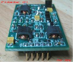
K3 H Mode Mixer
|
The price of the H mode mixer is about $193, delivered.
I am surprised there have been no comments on the value of swapping out the original mixer board for the H Mode mixer. It appears there is a performance improvement. But is the improvement really a big deal? The K3 is at the top of the performance heap. Would it be at least worth bragging rights to tweak it a bit? Mark, NØOKS ______________________________________________________________ Elecraft mailing list Home: http://mailman.qth.net/mailman/listinfo/elecraft Help: http://mailman.qth.net/mmfaq.htm Post: mailto:[hidden email] This list hosted by: http://www.qsl.net Please help support this email list: http://www.qsl.net/donate.html |
|
Thank you very much for your comments.
Wayne recognized interesting results when we reported yhe MDS, DR and IP3 comparison figures. We have to appreciate his comment “A few K3 users in extremely high-signal environments might benefit from a few extra dB of dynamic range, at the cost of a mixer add-on module like you described”, this may reply to your question. The K3 is a high performance radio and for this is very interesting. We are amateur radio and we like to “squize” equipment to see if we can get dome extra functionalities. With a radio like the K3 we cannot expect to have improuvements of tens of dB/dBm, like it is possible with other commercial equipment, following similar mods. As you can see we can still squize out something. We are not doing business, only enjoying radio and we like to share our findings with others Hams. We went into the K3 1st mixer mod because it is really the easiest we can apply to a radio…real swap with no soldering iron. 
We tried to measure spuries as suggested by Wayne but we were not sure about differences. We decided to do other tests that may help to understand if the improuvements are beneficial or not. Please see the second table figures. The improuvements are not only instrumental but also detectable by ears. The nearly 6dB in noise drop at the loudspeaker is something valuable and can be felt. K3 ORIGINAL MIXER AND 2T H-MODE MIXER COMPARISON TABLE 1 Measurements RF in 14.220 MHz Original K3 Mixer originale 2T H-Mode Mixer FSA3157 MDS (Sensibilita’) -126dBm -128dBm * Dynamic Range 2T 98dB 101dB 3rd Order Intercept IP3 +21.0dBm +23.5dBm (*Audio Noise at output dropped <6dB) TABLE 2 Frequency RF in 14.220MHz Original K3 Mixer originale 2T H-Mode Mixer FSA3157 RF in -40dBm -40dBm IF out 8.215 MHz -44.5dBm -44dBm 30MHz noise level line -80dBm -83dBm RF feedthrough/leakage -72.0dBm Into the noise level LO feedthrough/leakage 22.415MHz -49.0dBm -62.8dBm RF+LO 36.615MHz -57.0dBm -69.0dBm 2xLO 44.830MHz feedthrough/leakage -54.0dBm -63.6dBm 53.045MHz feedthrough/leakage -62.0dBm Into the noise level (The 2T H-Mode Mixer has a diplexer termination) What else?....This is the spirit of amateur radio and nothing more Saluti (73) Sergio, IK8TNG |
|
In reply to this post by N0OKS
Could someone please post a link to where this mixer is offered for sale? I'd be potentially interested in adapting it for other radios, not the K3. Thanks & 73, Barry N1EU |
|
Hi Barry,
If you are interested in a 2T H-Mode Mixer to modify other equipment, a different parts kit to be assembled is available. I have studied and applied mods to different commercial equipment:.. ICOM (IC751, 761, 765, 781, 775, YAESU (FT1000MP-MK-Field, FT920), KENWOOD (TS850, TS940), Elecraft K2 and others. You can contact me directly to my address i7swx@yahoo.com. 73 Gian I7SWX |
|
What's the difference between an "H" mode mixer and a ring mixer?
Jack WA9FVP
Sent from my home-brew I5 Core PC |
|
Hi Jack,
tank for your question. Basically the difference between the Ring Mixer and the H-Mode Mixer is: 1) In the ring mixer the mixing is performed by the semiconductors (diodes or fets) 2) In the H-Mode Mixer the mixing is performed by the transformers. The semiconductors (FET SW) are switching one side of the windings to ground. This has the benefit of not having the RF modulating the LO signal and not requiring higher voltage to switch on or switch off the FET. This is an important aspect as it reduces the possibility of LO phase noise and, consequently, reduces reciprocal mixing. The K3 1st mixer, a FET ring mixer, and the H-Mode mixer are commutative mixer, as their operation depends on switches. The FET array ring mixer was developed in the 80s by Ed Oxner, using an SD8901, with a conversion loss of -8/-9dB and an IP3 around +30dBm. The H-Mode Mixer was invented around 1993 by Colin Horrabin, G3SBI, using the SD5000 FET array IC, presenting a conversion loss of -8/-9dB and an IP3 of around +50dBm. The “H” has no technological meaning, it is coming from the look of the circuit diagram as the original 3 transformer configuration looks like an H. It was simplified when I had the idea of using Fast Bus Switches for mixers, with particular use of FST3125, by middle of 1998. This solution presented a conversion loss of around -5dB and an IP3 of around +40/45dBm. The “H” look is lost with the 2T HM Mixer but the functionality is there. The 2T H-M M was presented by me in 2003, presenting a conversion loss of around -5dBm and an IP3 of around +40dBm. Recently, Martein, PA3AKE, implemented an H-Mode Mixer version using analog switches FSA3157, with a conversion loss around -4.5dB and an IP3 of up to +50dBm. You can read a very extensive information visiting http://martein.home.xs4all.nl/pa3ake/hmode/hmode_intro.html. A simple and easy to understand description of the H-Mode Mixer is described in EMRF Design Book, W7ZOI et al published by ARRL. Several articles were published in RadCom, in the G3VA Column Technical Topics and also in QEX. G3SBI, thanks to the H-Mode Mixer, removed the mixer from the critical stages of a receiver. Hope I have clarified your question. Best 73 Gian I7SWX |
|
In reply to this post by N0OKS
Are both VFO's in FM mode? Rob NV5E ---------------------------------------- > From: [hidden email] > Date: Sat, 15 Oct 2011 17:24:32 -0700 > To: [hidden email] > Subject: [Elecraft] K3 split on FM > > This afternoon, I saw T32C on 10M FM, 29.580.. They were running split (actually several split frequencies over the time I was listening). The signal was a solid 59 for a while in Northern California. I tried to set to Split mode with the transmit frequency high, and got a "Split N/A" message. Checked through the K3 manual about FM and Split and saw nothing that would help. Split works fine in USB on all bands. I have not run FM before on the rig, so there may be something obvious that I overlooked. Yes, I do have the FM filter installed. > > Any help appreciated. > > 73s > > Randy K6CRC > K3#2051 > [hidden email] > > > > > ______________________________________________________________ > Elecraft mailing list > Home: http://mailman.qth.net/mailman/listinfo/elecraft > Help: http://mailman.qth.net/mmfaq.htm > Post: mailto:[hidden email] > > This list hosted by: http://www.qsl.net > Please help support this email list: http://www.qsl.net/donate.html ______________________________________________________________ Elecraft mailing list Home: http://mailman.qth.net/mailman/listinfo/elecraft Help: http://mailman.qth.net/mmfaq.htm Post: mailto:[hidden email] This list hosted by: http://www.qsl.net Please help support this email list: http://www.qsl.net/donate.html |
|
In reply to this post by I7SWX
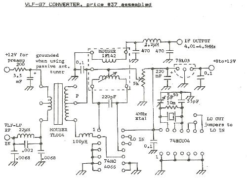
The reason that I ask is because I have a Bruhan's VLF converter that uses, what he called, a ring mixer. The Burhan's converter has a MC4066 analog switch where the control inputs of two fet switches are inverted and the other two are non inverted. When I saw the schematic of the H mode mixer, it reminded me of the Burhan's VLF converter. The difference is the transformers that Burhans used. They were audio transformers that covered the VLF range.
Jack WA9FVP
Sent from my home-brew I5 Core PC |
|
Hi Jack,
OK for everything. I do not know the Bruhan's VLF converter but I guess I understood how it maybe made. I have used an MC4066 for an SSB demodulator in my modified FT726R. The Ron is very high, on the hundreds ohm. I have also used the 74HC4066 to replace it and also used it as a mixer for a diect conversion rx. This IC has a lower Ron, severan tens of ohms. The Fst3125 presents, usually, an Ron of around 5 ohm, this is important for a lower conversion loss. I would be interested on the circuit diagram od the Bruhan's VLF converter, there is always something to learn. Thanks and best 73 Gian I7SWX
|
|
Here's the schematic. I purchased it in 1983. I was wrong he used a 74HC4066

Jack WA9FVP
Sent from my home-brew I5 Core PC |
|
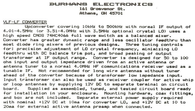
Here's the circuir description. Again, I was wrong, he called it a balanced mixer, not a ring mixer.

Jack WA9FVP
Sent from my home-brew I5 Core PC |
|
Hi Jack,
thanks for the circuit diagram and info on the converter. You should not feel sorry if you did not remember the right IC p/n and type of mixer....20 years of space are a long time to remember small particulars...hi Thanks again for the discussion and best 73 Gian I7SWX |
|
I still use the Burhans converter along with my K3 to copy VLF. I'm feeding the converter into the receive input on my K3. Lately I have been using the MULTIPSK software by F6CTE to decode MSK in the 300KHz range. It's abit out of the realm of Ham Radio but it's something I've done for years.
You can download the software at, http://f6cte.free.fr/index_anglais.htm
Jack WA9FVP
Sent from my home-brew I5 Core PC |
|
Hi Jack,
again thanks a lot for the circuit diagram and description of converter. Thanks for the link to the F6CTE software. I am not using PSK ... I am a chatter...hi I believe if something is old it does not mean is not good ... we can always modify it...hi 73 Gian I7SWX |
«
Return to [K3]
|
1 view|%1 views
| Free forum by Nabble | Edit this page |

