Erratic transmit power -- ALC oscillating?
Posted by n7zf on Feb 10, 2011; 9:00pm
URL: http://elecraft.85.s1.nabble.com/Erratic-transmit-power-ALC-oscillating-tp6013475.html
This is a new build of a rev A K2 (installed rev B mods), rework eliminators, no options installed, several other mods installed including the CW waveform keying mod (VALC circuit). Receiver is working well.
If I set the output power to 5 watts, the usually K2 reports the power as 4.2 watts or 6.3 watts -- sometimes 5.1 watts. I am seeing some unexpected things in the ALC circuit on the control board and am wondering if the ALC is causing the transmit power to fluctuate.
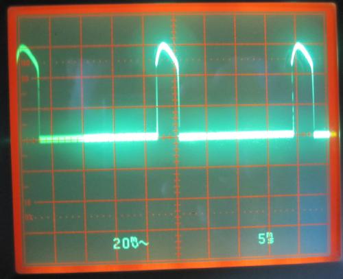
In both transmit (cw) and receive mode, on all bands, there is a 45 hertz 0.7 volt spike coming out of U10A (LMC660), causing Q8 to turn on for about 3.5 msecs every 22 msecs. The B-E junction of Q8 is limiting the spike voltage. See photo of signal on pin 1 of U10 -- same as base of Q8. Using a 10x probe, so vertical scale is 200 mV per division, horizontal scale is 5 msec per division.
At the junction of R22 (82K) and R21 (270K) I am seeing a 1volt peak-to-peak signal being fed back by C46 (.01). Is this expected? I see this 'ripple' continue as a 150 mV peak at Test Point 2, and also on the output of the Xmit Mixer U10-pin4 during transmit. I have removed the control board and verified all the correct components against the Rev. H schematic. I have traced all the connections in that circuit. I have rechecked against the keying mod instructions. The CW key waveform modifications appear to be working correctly but is the ALC circuit supposed to be oscillating?
The CW keying mod (rev A 2/3/2004) specifies C31 to be .01 uF. The Rev A-to-B upgrade (rev E 4/29/2003) specifies C31 to be .047 uF. I assumed that the CW keying mod was a more robust change and followed it (so C31 is .01 uF).
Same problem running off a power supply or a battery. I have installed new power amp finals and new power amp bias transistors. I have carefully inspected T1-T4 in the final, including removing T3 and rewinding it. I have tested the low pass filters with a network analyzer and found no problems. I have measured and inspected the RF Output Detector circuit (and have the 1% resistor at R68 which measures to be 225.0 ohms).
I am grasping at straws at this point and would appreciate troubleshooting suggestions.
Bob N7ZF
URL: http://elecraft.85.s1.nabble.com/Erratic-transmit-power-ALC-oscillating-tp6013475.html
This is a new build of a rev A K2 (installed rev B mods), rework eliminators, no options installed, several other mods installed including the CW waveform keying mod (VALC circuit). Receiver is working well.
If I set the output power to 5 watts, the usually K2 reports the power as 4.2 watts or 6.3 watts -- sometimes 5.1 watts. I am seeing some unexpected things in the ALC circuit on the control board and am wondering if the ALC is causing the transmit power to fluctuate.
In both transmit (cw) and receive mode, on all bands, there is a 45 hertz 0.7 volt spike coming out of U10A (LMC660), causing Q8 to turn on for about 3.5 msecs every 22 msecs. The B-E junction of Q8 is limiting the spike voltage. See photo of signal on pin 1 of U10 -- same as base of Q8. Using a 10x probe, so vertical scale is 200 mV per division, horizontal scale is 5 msec per division.
At the junction of R22 (82K) and R21 (270K) I am seeing a 1volt peak-to-peak signal being fed back by C46 (.01). Is this expected? I see this 'ripple' continue as a 150 mV peak at Test Point 2, and also on the output of the Xmit Mixer U10-pin4 during transmit. I have removed the control board and verified all the correct components against the Rev. H schematic. I have traced all the connections in that circuit. I have rechecked against the keying mod instructions. The CW key waveform modifications appear to be working correctly but is the ALC circuit supposed to be oscillating?
The CW keying mod (rev A 2/3/2004) specifies C31 to be .01 uF. The Rev A-to-B upgrade (rev E 4/29/2003) specifies C31 to be .047 uF. I assumed that the CW keying mod was a more robust change and followed it (so C31 is .01 uF).
Same problem running off a power supply or a battery. I have installed new power amp finals and new power amp bias transistors. I have carefully inspected T1-T4 in the final, including removing T3 and rewinding it. I have tested the low pass filters with a network analyzer and found no problems. I have measured and inspected the RF Output Detector circuit (and have the 1% resistor at R68 which measures to be 225.0 ohms).
I am grasping at straws at this point and would appreciate troubleshooting suggestions.
Bob N7ZF
| Free forum by Nabble | Edit this page |