New KX1 low power and 20m oscillation

12

12
New KX1 low power and 20m oscillation

|
Just finished building the KX1 and the transmit testing is not going well. My only bench tool is a DVM.
Power supply is a 13V battery. Ant is a 50 ohm dummy load. The receiver seems to work fine. All DC voltages on RX are nominal. On 40m TX, I get about 1.5W out. The signal is clean listening with my K3. On 20m TX, I get about 2W out but there is a horrendous audio oscillation. My P3 shows huge sidebands on the signal. All the TX DC voltages look good EXCEPT for the base of Q7, which is supposed to be 0.7V. I measure -0.895V on 40 and -0.195 on 20. I have examined all the suggested areas, but I don't find any obvious problems. Anybody have a suggestion of a cause of this behavior?
73, Stan - KR7C
|
Re: New KX1 low power and 20m oscillation
|
|
I may have been a bit hasty in concluding that there were oscillations on 20m; after I disconnected my K3's 20m antenna, the 20m signal looks fine. So I may have just been overloading the K3's front end. Not sure why the 40m signal didn't suffer the same issue, though.
Still have a very low power output (1.7W 40m, 2.0W 20m) and I've done all the suggested troubleshooting in the manual. Components all look in their proper places and well soldered.
73, Stan - KR7C
|
Re: New KX1 low power and 20m oscillation
|
|
Stan,
I was not available yesterday, so could not respond to your initial post. The problem is most likely in the Low Pass Filter, so count the turns on L1 and L2 very carefully - count the number of times the wire passes through the center of the core. Double check the capacitors in the LPF for correct values. You might want to check the current draw during transmit. Assume the PA transistor should be 50% efficient and there is another 100 ma being used by the DDS and other circuits, 2 watts should require a total on 500 ma. If the current draw is greater than that, the Low Pass Filter has a problem and is shunting some of the power to ground. OTOH, if the current is commensurate with the power produced then the solution will be found in the Q4 Q5 circuits or the DDS. Going back to your earlier conclusion that there were oscillations - yes, that can happen and can give erroneous power indications. If you were to look at the output on a scope and find the RF waveform looks "modulated", you can be certain the LPF is not suppressing the harmonics. 73, Don W3FPR On 5/6/2012 6:29 PM, Stan Gibbs wrote: > I may have been a bit hasty in concluding that there were oscillations on > 20m; after I disconnected my K3's 20m antenna, the 20m signal looks fine. > So I may have just been overloading the K3's front end. Not sure why the > 40m signal didn't suffer the same issue, though. > > Still have a very low power output (1.7W 40m, 2.0W 20m) and I've done all > the suggested troubleshooting in the manual. Components all look in their > proper places and well soldered. > ______________________________________________________________ Elecraft mailing list Home: http://mailman.qth.net/mailman/listinfo/elecraft Help: http://mailman.qth.net/mmfaq.htm Post: mailto:[hidden email] This list hosted by: http://www.qsl.net Please help support this email list: http://www.qsl.net/donate.html |
Re: New KX1 low power and 20m oscillation
|
|
The 20m waveform on my P3 seems very broad, but I don't think that it is due to any kind of oscillation. The signal is 20 KHz wide at about 40 dB down. I don't know if this is normal or not, but I did manage to make 20m and 40m QSOs last evening with good signal reports for both.
I made the power mod and the 40m power is now 2.8W and 20m power is 3.2W. Probably adequate for my SOTA needs.
73, Stan - KR7C
|
Re: New KX1 low power and 20m oscillation
|
|
I meant to say 2KHz wide, not 20... Here is a picture for those who might be interested: 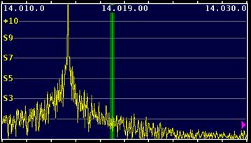
73, Stan - KR7C
|
Re: New KX1 low power and 20m oscillation
|
|
In reply to this post by Stan Gibbs, KR7C
Stan,
Do you have the proper number of turns on the LPF toroids. Count them and count again. I suspect you may have one extra turn giving you the lower power on 40 meters. I am not sure why you get the wide signal on 20 meters, because an extra turn on the toroids would reduce the cutoff frequency down into the 20 meter band. Count the number of times the wire passes through the center of the core. 73, Don W3FPR On 5/7/2012 8:10 PM, Stan Gibbs wrote: > The 20m waveform on my P3 seems very broad, but I don't think that it is due > to any kind of oscillation. The signal is 20 KHz wide at about 40 dB down. > I don't know if this is normal or not, but I did manage to make 20m and 40m > QSOs last evening with good signal reports for both. > > I made the power mod and the 40m power is now 2.8W and 20m power is 3.2W. > Probably adequate for my SOTA needs. > ______________________________________________________________ Elecraft mailing list Home: http://mailman.qth.net/mailman/listinfo/elecraft Help: http://mailman.qth.net/mmfaq.htm Post: mailto:[hidden email] This list hosted by: http://www.qsl.net Please help support this email list: http://www.qsl.net/donate.html |
Re: New KX1 low power and 20m oscillation
|
|
Hi Don,
All of the toroidal inductors and transformers have the correct number of turns.
73, Stan - KR7C
|
Re: New KX1 low power and 20m oscillation
|
|
Stan,
Thanks for checking. Try spreading the turns out evenly over the full diameter of the core. You should be able to achieve 3 watts or more on each band with a 13m8 volt power supply. 73, Don W3FPR On 5/7/2012 10:19 PM, Stan Gibbs wrote: > Hi Don, > > All of the toroidal inductors and transformers have the correct number of > turns. > > > > > ----- > 73, Stan - KR7C > -- > View this message in context: http://elecraft.365791.n2.nabble.com/New-KX1-low-power-and-20m-oscillation-tp7531133p7537532.html > Sent from the Elecraft mailing list archive at Nabble.com. > ______________________________________________________________ > Elecraft mailing list > Home: http://mailman.qth.net/mailman/listinfo/elecraft > Help: http://mailman.qth.net/mmfaq.htm > Post: mailto:[hidden email] > > This list hosted by: http://www.qsl.net > Please help support this email list: http://www.qsl.net/donate.html > Elecraft mailing list Home: http://mailman.qth.net/mailman/listinfo/elecraft Help: http://mailman.qth.net/mmfaq.htm Post: mailto:[hidden email] This list hosted by: http://www.qsl.net Please help support this email list: http://www.qsl.net/donate.html |
Re: New KX1 low power and 20m oscillation
|
|
Which core are we talking about? The manual says to "squeeze" the windings of L2 if the 40m power is lower than 20m. I tried that and it did seem to raise the 40m power, though still not as high as 20. I think some of the extra power on 20m is due to the spurious sidebands that I observe. I really would like to understand what is causing that phenomenon because it tells me something just isn't right and because I don't feel comfortable operating with such a signal, despite the fact that other stations give me good reports.
73, Stan - KR7C
|
Re: New KX1 low power and 20m oscillation
|
|
Stan,
Without a 'scope or Spectrum Analyzer connected to your KX1, I don't know haw to answer, but my best guess is that you have a 20 meter low pass filter that has a cutoff frequency that is lower than normal (spreading the LPF turns will help with that, while the LPF cutoff for 40 meters is too low for whatever reason or another, and that must be resolved. Run the KX1 into a dummy loaqd thaqt is known to be 50 ohms resistive at 7.000.000 aettinbe On 5/7/2012 11:22 PM, Stan Gibbs wrote: > Don Wilhelm-4 wrote >> Try spreading the turns out evenly over the full diameter of the core. >> > Which core are we talking about? The manual says to "squeeze" the windings > of L2 if the 40m power is lower than 20m. I tried that and it did seem to > raise the 40m power, though still not as high as 20. > > I think some of the extra power on 20m is due to the spurious sidebands that > I observe. I really would like to understand what is causing that phenomenon > because it tells me something just isn't right and because I don't feel > comfortable operating with such a signal, despite the fact that other > stations give me good reports. > > > ----- > 73, Stan - KR7C > -- > View this message in context: http://elecraft.365791.n2.nabble.com/New-KX1-low-power-and-20m-oscillation-tp7531133p7537625.html > Sent from the Elecraft mailing list archive at Nabble.com. > ______________________________________________________________ > Elecraft mailing list > Home: http://mailman.qth.net/mailman/listinfo/elecraft > Help: http://mailman.qth.net/mmfaq.htm > Post: mailto:[hidden email] > > This list hosted by: http://www.qsl.net > Please help support this email list: http://www.qsl.net/donate.html > Elecraft mailing list Home: http://mailman.qth.net/mailman/listinfo/elecraft Help: http://mailman.qth.net/mmfaq.htm Post: mailto:[hidden email] This list hosted by: http://www.qsl.net Please help support this email list: http://www.qsl.net/donate.html |
Re: New KX1 low power and 20m oscillation
|
|
In reply to this post by Stan Gibbs, KR7C
Stan,
Looking at your KX1's 20m Tx spectrum shown in your picture, my impression is that the wide pedestal in the bottom part could be due to phase noise. I will return to this later. However as I do not own a P3, which I think you are using, I am not familiar with how signals "look" on the P3 and whether or not some characteristic of the P3 is contributing to the wide pedestal. Does your KX1's Tx spectrum look "narrower" on the other bands? 73, Geoff LX2AO On May 08, 2012 at 02:10 +0200, Stan Gibbs wrote: > The 20m waveform on my P3 seems very broad, but I don't think that it is > due > to any kind of oscillation. The signal is 20 KHz wide at about 40 dB > down. > I don't know if this is normal or not, but I did manage to make 20m and > 40m > QSOs last evening with good signal reports for both. <snip> ______________________________________________________________ Elecraft mailing list Home: http://mailman.qth.net/mailman/listinfo/elecraft Help: http://mailman.qth.net/mmfaq.htm Post: mailto:[hidden email] This list hosted by: http://www.qsl.net Please help support this email list: http://www.qsl.net/donate.html |
Re: New KX1 low power and 20m oscillation
|
|
Here is a shot of my KX1's 40m signal:
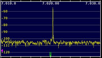 Clearly, the signal is much cleaner than 20m. Here is another shot of the 20m signal at a 2 KHz span: 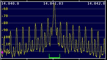 Anybody have an idea for the possible source of this modulation?
73, Stan - KR7C
|
Re: New KX1 low power and 20m oscillation
|
|
Stan,
Check the low pass filter components carefully. It is possible that it is letting harmonics through. Make certain that Q7 is working. Capacitor CA is one of the low pass filter components that must be in the circuit on transmit. Q7 effectively grounds one side of that capacitor on transmit. 73, Don W3FPR On 5/8/2012 11:16 AM, Stan Gibbs wrote: > Here is a shot of my KX1's 40m signal: > > http://elecraft.365791.n2.nabble.com/file/n7539479/KX1_40m.jpg > > Clearly, the signal is much cleaner than 20m. > > Here is another shot of the 20m signal at a 2 KHz span: > > http://elecraft.365791.n2.nabble.com/file/n7539479/KX1_20m.jpg > > Anybody have an idea for the possible source of this modulation? > Elecraft mailing list Home: http://mailman.qth.net/mailman/listinfo/elecraft Help: http://mailman.qth.net/mmfaq.htm Post: mailto:[hidden email] This list hosted by: http://www.qsl.net Please help support this email list: http://www.qsl.net/donate.html |
Re: New KX1 low power and 20m oscillation
|
|
As I said in my original post, Q7 is the place where my DC troubleshooting measurements differed from specs. The base of Q7, which is supposed to be 0.7V, is -0.895V on 40 and -0.195 on 20. The voltage on Q7 should definitely be positive in order for it to ground capacitor CA, so something is screwy. Someone suggested that either C45 or C32 were possibly bad, allowing RF on to the base of Q7, which might cause the bogus voltages. I tried adding additional capacitance in parallel with C45/C32, but that had no effect.
73, Stan - KR7C
|
Re: New KX1 low power and 20m oscillation
|
|
Hello Stan,
If Q7 is not conducting and is not in effect grounding one side of CA, then a loop is created between the input (Q1 Gate) and output stage of the transmitter. Part of this loop contains the Rx RF Gain pot R1, the Rx's input tuned circuit, and the coupling between pins 1 and 6 of U6 be it inside or external to the chip. To eliminate (or not) the possibility that on 20m transmitter is unstable because Q7 is not removing this loop, I suggest that while transmitting you wind down the Rx RF Gain pot R1 to see if the spectrum improves. I am curious as to why the sidebands on 20m are spaced at 60 Hz intervals. 73, Geoff LX2AO On May 08, 2012 at 18:07 +0200, Stan Gibbs wrote: > As I said in my original post, Q7 is the place where my DC troubleshooting > measurements differed from specs. The base of Q7, which is supposed to be > 0.7V, is -0.895V on 40 and -0.195 on 20. The voltage on Q7 should > definitely be positive in order for it to ground capacitor CA, so > something > is screwy. > > Someone suggested that either C45 or C32 were possibly bad, allowing RF on > to the base of Q7, which might cause the bogus voltages. I tried adding > additional capacitance in parallel with C45/C32, but that had no effect. ______________________________________________________________ Elecraft mailing list Home: http://mailman.qth.net/mailman/listinfo/elecraft Help: http://mailman.qth.net/mmfaq.htm Post: mailto:[hidden email] This list hosted by: http://www.qsl.net Please help support this email list: http://www.qsl.net/donate.html |
Re: New KX1 low power and 20m oscillation
|
|
Actually, there is an easier test - just put a temporary jumper between
the connector and emitter of Q7. Do not expect it to receive with that jumper in place, but observe what happens to the sidebands when you transmit. If it cleans things up with the jumper in place, replace Q7 and make certain R28 is well soldered. Stan reported a negative voltage on the base of Q7 - I trust that was while transmitting, and if that assumption is true, I suspect R28 has a problem. One end of R28 should be near 6 volts when transmitting and the other end should be near 0.6 volts. 73, Don W3FPR On 5/8/2012 7:39 PM, Geoffrey Mackenzie-Kennedy wrote: > Hello Stan, > > If Q7 is not conducting and is not in effect grounding one side of CA, then > a loop is created between the input (Q1 Gate) and output stage of the > transmitter. Part of this loop contains the Rx RF Gain pot R1, the Rx's > input tuned circuit, and the coupling between pins 1 and 6 of U6 be it > inside or external to the chip. > > To eliminate (or not) the possibility that on 20m transmitter is unstable > because Q7 is not removing this loop, I suggest that while transmitting you > wind down the Rx RF Gain pot R1 to see if the spectrum improves. > > I am curious as to why the sidebands on 20m are spaced at 60 Hz intervals. > > 73, > > Geoff > LX2AO > > > > On May 08, 2012 at 18:07 +0200, Stan Gibbs wrote: > > >> As I said in my original post, Q7 is the place where my DC troubleshooting >> measurements differed from specs. The base of Q7, which is supposed to be >> 0.7V, is -0.895V on 40 and -0.195 on 20. The voltage on Q7 should >> definitely be positive in order for it to ground capacitor CA, so >> something >> is screwy. >> >> Someone suggested that either C45 or C32 were possibly bad, allowing RF on >> to the base of Q7, which might cause the bogus voltages. I tried adding >> additional capacitance in parallel with C45/C32, but that had no effect. > ______________________________________________________________ > Elecraft mailing list > Home: http://mailman.qth.net/mailman/listinfo/elecraft > Help: http://mailman.qth.net/mmfaq.htm > Post: mailto:[hidden email] > > This list hosted by: http://www.qsl.net > Please help support this email list: http://www.qsl.net/donate.html > Elecraft mailing list Home: http://mailman.qth.net/mailman/listinfo/elecraft Help: http://mailman.qth.net/mmfaq.htm Post: mailto:[hidden email] This list hosted by: http://www.qsl.net Please help support this email list: http://www.qsl.net/donate.html |
Re: New KX1 low power and 20m oscillation
|
|
But that requires the use of solder :-)
73, Geoff LX2AO On May 09, 2012 at 02:02 +0200, Don Wilhelm wrote: > Actually, there is an easier test - just put a temporary jumper between > the connector and emitter of Q7. Do not expect it to receive with that > jumper in place, but observe what happens to the sidebands when you > transmit. If it cleans things up with the jumper in place, replace Q7 > and make certain R28 is well soldered. > > Stan reported a negative voltage on the base of Q7 - I trust that was > while transmitting, and if that assumption is true, I suspect R28 has a > problem. One end of R28 should be near 6 volts when transmitting and > the other end should be near 0.6 volts. > > 73, > Don W3FPR ______________________________________________________________ Elecraft mailing list Home: http://mailman.qth.net/mailman/listinfo/elecraft Help: http://mailman.qth.net/mmfaq.htm Post: mailto:[hidden email] This list hosted by: http://www.qsl.net Please help support this email list: http://www.qsl.net/donate.html |
Re: New KX1 low power and 20m oscillation
|
|
Sooo??? - the KX1 is a "solder" type kit. It is the KX3 that is "no
solder".:-) I meant to say "collector" instead of "connector" - please forgive - actually my excuse is that the letters are wearing off my keyboard and I am not fully a touch typist - only halfway there, so you pardon the mistypes. The "E", "A". "N", and "M" are completely worn off and the "C" is only half there. 73, Don W3FPR On 5/8/2012 8:36 PM, Geoffrey Mackenzie-Kennedy wrote: > But that requires the use of solder :-) > > 73, > Geoff > LX2AO > > > On May 09, 2012 at 02:02 +0200, Don Wilhelm wrote: > > >> Actually, there is an easier test - just put a temporary jumper >> between the connector and emitter of Q7. Do not expect it to receive >> with that jumper in place, but observe what happens to the sidebands >> when you transmit. If it cleans things up with the jumper in place, >> replace Q7 and make certain R28 is well soldered. >> >> Stan reported a negative voltage on the base of Q7 - I trust that was >> while transmitting, and if that assumption is true, I suspect R28 has >> a problem. One end of R28 should be near 6 volts when transmitting >> and the other end should be near 0.6 volts. >> >> 73, >> Don W3FPR > > Elecraft mailing list Home: http://mailman.qth.net/mailman/listinfo/elecraft Help: http://mailman.qth.net/mmfaq.htm Post: mailto:[hidden email] This list hosted by: http://www.qsl.net Please help support this email list: http://www.qsl.net/donate.html |
Re: New KX1 low power and 20m oscillation
|
|
In reply to this post by Don Wilhelm-4
Don, I tried your experiment but it had no effect. I just grounded point A because it is damn hard to jumper Q7. R28 measures good and is well soldered. It has -0.25V or so on the base side and 5.5V on the other during transmit.
I also tried reducing the drive pot and, while the signal definitely declined in amplitude, the sidebands were still present. Could this just be an artifact of using my K3/P3 to view the waveform? If so, why would the 40m signal be so different?
73, Stan - KR7C
|
|
|
Stan, Just to recap my earlier thoughts, I think your Q7 is fine, the negative voltage is a red herring. It's due to the RF that is being grounded via Q7 (its task). Do you know any other hams who might tell what their Q7 DC voltage is, from functioning rigs? I gave you mine and they match yours within a reasonable tolerance. I will see if I can get to a ham with a scope and report to you when I can, maybe this weekend. In the mean time, I'd get up a hill! 73, Ian MM0GYX |
«
Return to [KX1]
|
1 view|%1 views
| Free forum by Nabble | Edit this page |